Note: References to "turnout" in this documentation include all types, including slips and cross-overs.
NX Routing builds a dynamic valid path between two locations on a Layout Editor panel. The path can traverse a number of Turnouts and different Blocks. The Entry and Exit locations on the Layout Editor are defined by the placement of Sensors at various Block boundaries. When two Sensors are activated and a clear and valid route is found between them, then the Turnouts in the route will automatically be set accordingly. If the path between the two sensors was created with the type set to Full Interlock, then the blocks will be reserved and will display a different track color.
If there are multiple paths between two locations, then the system will use the path with the smallest cost or number of different Blocks. If one of the Blocks on the path is already occupied and there is a valid alternative path, then this will be taken.
The two sensors are referred to as a NX Pair.
since 4.11.1It is also possible to define a NX pair where the destination sensor is on another panel. This requires that the panels are linked using Edge Connectors.
There are three different types of Entry/Exit pairs that can be configured.
Turnout Only — With turnout only, the NX Pair will only set the turnouts to the correct state for that route. If a block is already showing as occupied or reserved within that route, and an alternative one is available then the alternative route will be set, otherwise the route will not be set.
Turnout and SignalMast Logic — This option includes what is covered by "Turnout Only" and will also generate the SignalMast Logic for that route. The logic will include the turnout states and the blocks that are within that route. For this to work, SignalMasts must also be placed at the same boundary points as the sensors working in the same direction. The SignalMast logic will remain for the duration of the operating session, however it is not saved and will be re-created the next time the panel is opened. When there is no route set then the SignalMast will be placed in a held state if the Use ABS Signal Mode option is not selected.
Full Interlocking — This covers the same things as the other two items above. In addition, it will also "reserve" or "lock out" each block in the route so that no other conflicting route can be set. If block occupancy detection is being used the route will automatically be cleared down. If no block occupancy is being used, then it is possible to manually clear the route down by selecting the corresponding NX pair, it will leave the last block as showing occupied, as if the train had travelled the route and was now sitting waiting at the next signal. If there are no Signalmasts configured between the NX pair, then the route will still be set and reserved, but no SignalMast Logic will be generated. The route will stay active, until either a train has passed through the blocks and they have returned to an unoccupied state, the route has been manually cleared down, or has been cancelled. The normal mode for related signal mast is to keep the mast in a Held state until a route has been created, at which time the hold is released. When the first block becomes occupied the hold is set. If the Use ABS Signal Mode option is selected, the signal masts will not be held. If all of the NX Pairs related to a source mast are disabled, then the hold for the mast is released, effectively setting the mast to ABS mode.
For the second and third types, if the signal mast logic has already been created, temporary signal mast logic will not be created.
Sensors, along with Signal Heads and Signal Masts, can be added at Block Boundaries. Block boundaries can occur at Anchor Points, Turnouts, Level Crossings and End Bumpers. Edge Connectors are always a block boundary.
Sensors are assigned to anchor points, end bumpers and edge connectors by right clicking on the small colored box that represents the point and select Set Sensors.... For end bumpers there will be one choice to make. Anchor points and edge connectors provide two choices.
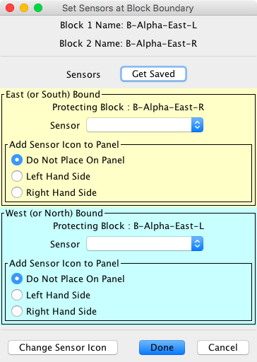
Select the sensor name that will be used to protect the desired block. This becomes the entry sensor for routes starting with this block. It is also the exit sensor for routes that end before the desired block. Note: For edge connectors, ignore the East and West reference. Use only the Protecting Block to determine which section to use.
Turnouts and level crossings can have from zero to four block boundaries. If a track segment is attached to a turnout leg and it has been assigned the same block as the turnout itself, there will not be a boundary for that leg.
Right click the turnout or level crossing and select Set Sensors....
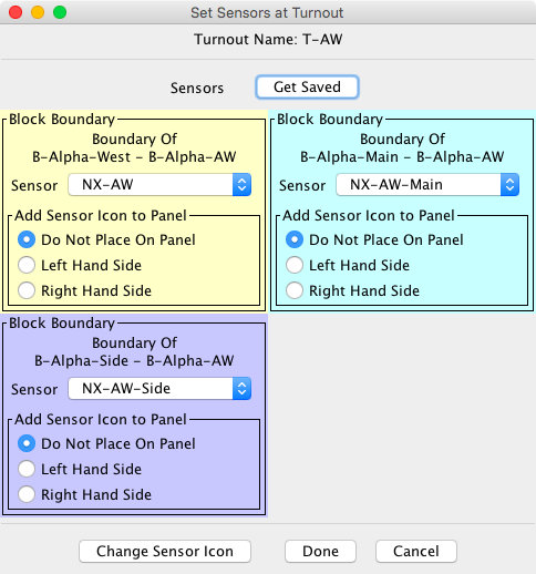
For turnouts and level crossings, the protected block is the block that contains the turnout or level crossing. In other words, sensors are for the boundary going into the turnout or crossing. It is not possible to add a sensor for the boundary going out from the turnout or crossing.
Removing an Entry/Exit sensor from the Layout Editor panel requires that the Entry/Exit pairs that use the sensor are removed from the Entry/Exit list. If any affected Entry/Exit pair is being used in a Logix Conditional, the sensor removal process is stopped.
The primary method for deleting an Entry/Exit sensor is to right click on the icon and select Remove. A dialog box is displayed with 3 buttons.
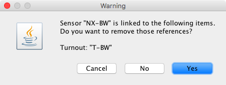
Select Cancel to stop the delete process, No to delete the icon but leave the sensor reference, or Yes to delete the icon and the sensor reference.
The other method to delete a sensor is to use the Set Sensors... option described above and select either a different sensor or the blank row at the top of the sensor list.
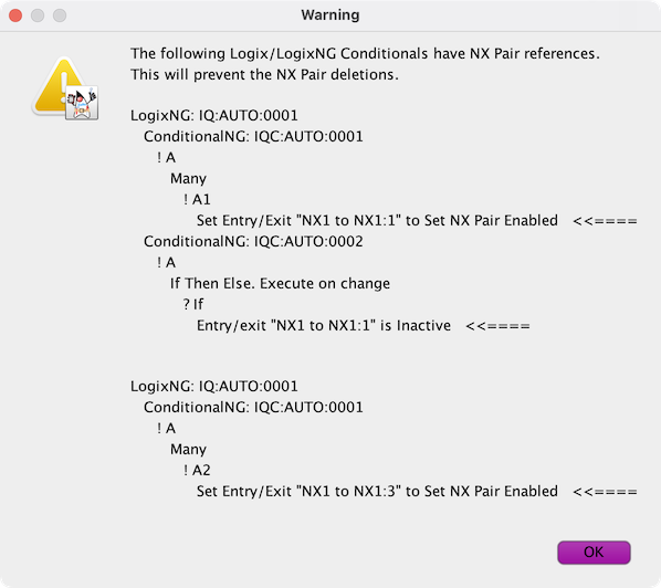
Before the delete process can begin, the Entry/Exit pairs that use the selected sensor cannot be used in any Logix Conditional. If any are used, a list of the Conditionals is displayed and the delete process is terminated.
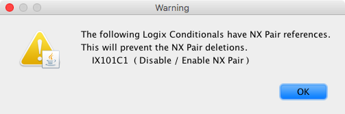
The same check applies to LogixNG expressions and actions.
The next step in the delete process will provide a list of the Entry/Exit pairs that will be deleted if the sensor is deleted.
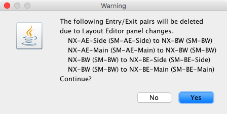
Select No to terminate the delete process, Yes to finish the delete process.
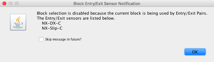
Sensor assignments define Entry/Exit locations within the layout block structure. If an Entry/Exit pair contains references to the block, the block name cannot be renamed or removed. The block selection field in the Edit Track dialog will be disabled. A dialog box will be displayed showing the affected sensors.
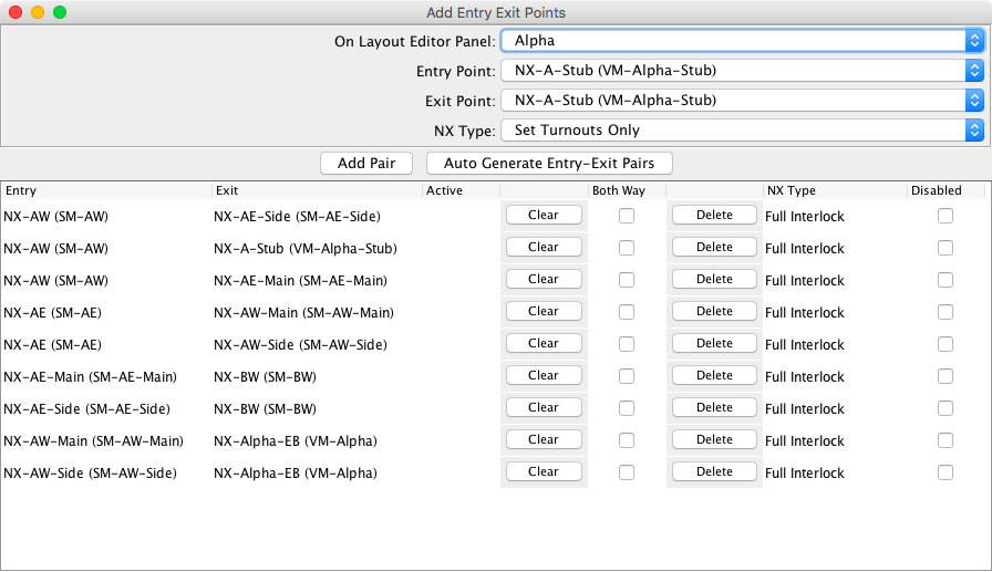
To access the Add Entry Exit Points panel, select Entry Exit from the Layout Editor Tools menu. Entry/Exit pairs can be created manually using the Add Pair button or automatically using the Auto Generate Entry-Exit Pairs button.
For additional details, see Entry/Exit (NX) Tools
Auto Generate Entry-Exit Pairs will discover all the valid Entry Exit pairs on the Layout Editor layout. Using the combo boxes it is also possible to manually add in additional Entry Exit pairs.
In all cases when the Entry Sensor is set active followed by the Exit Sensor, the route will be set between those two points and the two Sensors will return back to the "Inactive" state.
If the Both Way option is ticked, a reversed route can be selected by clicking on the Exit sensor and then the Entry sensor. Both Way cannot be selected if either block boundary also has a signal assigned or the destination is at an end bumper.
With the manual method, it is possible to create invalid pairs. Invalid pairs will never be used.
since 5.5.7The manual selections will be validated after the NX pair has been added. If the validation fails, a dialog will be displayed.
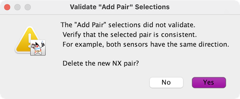
Click on Yes to delete the NX pair that was just added. Click on No to skip the delete. This might be needed in certain cases where the validation detects a false positive validation failure.
Once the NX pairs have been created, a route can be set by selecting the Entry Sensor, followed by the Exit Sensor. When the entry sensor is selected, it will start flashing. When the exit sensor is selected, a route will be created if possible. If a valid route cannot be found, both sensors will return to the inactive state. If a valid path can be found then the route will be set up according to how it has been configured. If full interlock has been configured for the NX Pair the sensors will remain active and the track components will be assigned the alternate track color.
Whenever an entry NX Sensor has been selected, it will flash until a valid exit sensor has been selected. If no valid exit sensor has been selected it will automatically be cancelled after 30 seconds.
Normally with the NX interlock, a route will be up by selecting the Entry/Exit sensors
along a path, so for example to get from location A to D, A-B would be selected, then B-C and
finally C-D. However the system will allow the full route to be set up by selecting A and D.
The system will then go through and find the best valid path and set up each individual
interlock along the path.
Note: If an extended route is cleared or cancelled, each segment will need
to be cancelled or cleared by responding to the prompt.
When using the Full Interlock NX type, re-selecting the entry and exit sensors will display a dialog box:
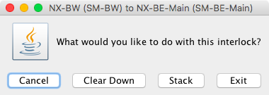
Options:
Pending route list:
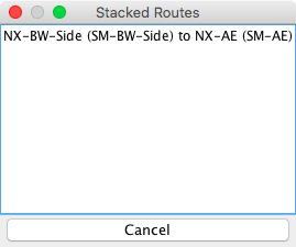
Once a route has been stacked, the system will check every 10 seconds to see if it is possible to set up that NX route. Multiple NX routes can be stacked, and they are checked in the order which they were stacked. An NX route cannot be stacked more than once. To cancel an NX route, select it in the table and click on the "Cancel" button at the bottom.
If a selected route tries to cross a block that is occupied or reserved and there is not an alternate route available, the Route Not Clear dialog box is displayed.
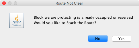
If Yes is selected, the route will be added to the pending route list. Note: Only single segment conflicts are detected. A multiple segment route request will not provide the stack option.
For LogixNG support see Expressions and Actions.