This brief tutorial is designed to explain how the Entry Exit and Interlocking is set up and works within JMRI. It is based upon the Signal Mast Logic clinic held in the UK and follows on from that.
The panel file for this tutorial was taken from the "Logix and Feathers" section of the Signal Mast tutorial. The only difference is that the Signal Mast Logic has been removed from all the Signal Masts apart from the "up outer mast" and the "down platform mast" as these are used to represent signals in automatically controlled areas.
In addition the file has been modified to use Internal Sensors and Turnouts only, thus allowing it to be opened with any system connection configured in the JMRI Preferences.
As a prerequisite the clinic on Signal Mast Logic should be followed before attempting this one as it provides the foundation on how to build your panel ready for use with the Signal Mast Logic and also Interlocking.
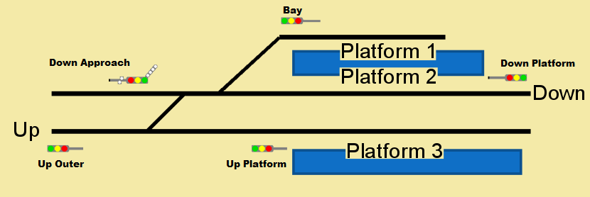
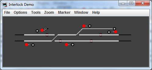
The track plan for this is the same as in the Signal Mast Logic clinic and could be considered a typical scenario where the Down Approach, Up Platform and Bay Signals would be under the control of the SignalMan, while the Up Outer and Down Platform would be automatically controlled.
The panel file for this tutorial can be found here
The NX buttons all work in pairs and must be selected in the correct order. Also it is not possible to leap-frog an NX button to set a Route between two non-adjacent buttons. I.e. if you have buttons A-B-C it is not possible to set a route from A to C, the order of selection must be A-B B-C.
In the Signal Mast Logic tutorial, each block was configured with a different color to show Occupied and Unoccupied states (Building a Layout). In addition it is possible to assign an alternative color to each Block on the panel. When using Full Interlocking, this alternative color is used to highlight routes that have been set. When a Block is using the alternative color it also prevents another route from being set using that Block.
The eNtry eXit (NX) utilises Sensors for each NX location, typically associated with a signal or an End Bumper/Buffer Stop. These Sensors would act in the same way as a button on a physical panel, setting the button active to start the selection with the setting Active of a second Sensor completing the route or path selection. If a matching Sensor is not activated within 10 seconds then the initial Sensor will be reset back to Inactive.
A sensor needs to be configured for each NX location. As a suggestion to help keep track of things, prefix the User Name with "NX" followed by the associated signal. So for example if the NX Sensor will be associated with the "Down Appr" signal, then make the Sensor User Name "NX Down Appr".
Once the Sensors have been created they can be associated and positioned with locations on the Layout Editor Panel, in the same way that the Signal Masts were done in part 6 of the Signal Mast Logic clinic. Bring up the context menu (right click) on the Block boundary and select "Set Sensors" from the list.

Remember that the Block which the Sensor is assigned to will determine the direction of
travel; if the Sensor is assigned to the incorrect Block then it will not get picked up and
the interlocks will not work.
The panel file with the Sensors already assigned can be found here
Open up the Entry Exit window, which can be found in the Tools menu of the Layout Editor. This will bring up a window like the following:
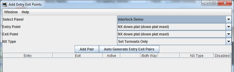
This window allows you to see which NX pairs have been created and the state of each pair. From this window we can get the system to automatically generate the pairs or we can manually define them.
If to start with you select "Set Turnout Only" and press "Auto generate Entry Exit Pairs", it will end up generating a list with four pairs like in the following illustration:
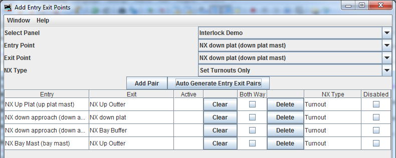
The four paths generated are all valid NX pairs based upon the direction of travel. For the NX to be set you must first select the Entry sensor, followed by the Exit sensor. If they are selected in the reverse order the path will not be set.
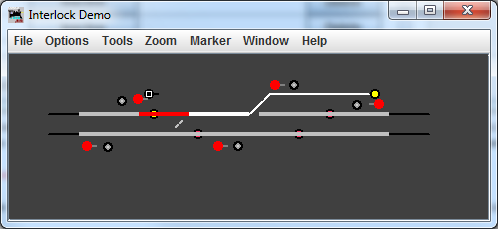
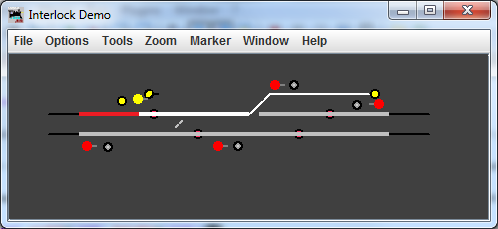
You can see that if you were to set a Route from the "down appr" to the bay buffer stop, the Turnouts get automatically set. The Sensors will also flash while the Route is being set up:
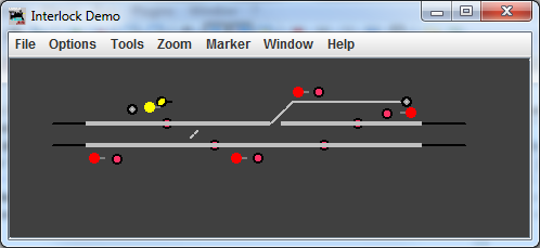
If you then set a Route from the "Bay Mast" to the "Up Appr", again the Turnouts will automatically be set:
With the Turnout Only interlock type, as no further logic or interlocking is done, it is possible to allow the interlock to be set up no matter which way round the NX buttons are selected. This can be done by selecting the "Both Way" flag in the table against an entry. You can then set the path in reverse, eg "NX Up Outer" to "NX Bay Mast".
In addition to this, with a "Turnout Only" set you can also create NX pairs that go against the normal direction of travel, for example from "Bay Mast" to "Down Appr"
If "Set Turnouts and Signal Masts" is selected and then the "Auto Generate" button is pressed, the same four interlocks will be generate, with the NX type set to "Signal Mast".
This time when you set the Route between two NX sensors, it will set the Turnouts and if Signal Masts are placed at the same location it also configures the logic from the Signal Mast at the source.
The Signal Mast Logic will appear in the Signal Mast Logic Table. This logic is not saved when the panel file is saved.
If you set a Route from "Down Appr" into the bay buffer stop, you will see that the Turnouts get set and the Signal changes to the correct Aspect. If you then change the state of the Turnout or Block on the path, you will see that the source Signal Mast will change Aspect appropriately.
If "Full Interlock" is selected and then the "Auto Generate" button is pressed, again you would end up with the four interlocks as before.
When a full interlock is configured and there are Signal Masts placed at the NX locations, Interlocking will place the Signal Mast at the source location into a Held state until a path has been set, which will in turn release the signal. This is working on the basis that these signals are now under the control of a SignalMan who has to set the appropriate Route before releasing the signal.
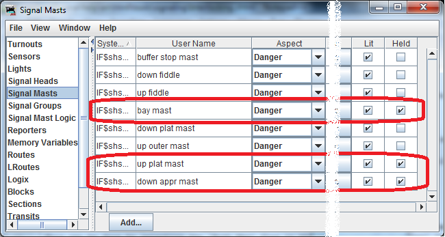
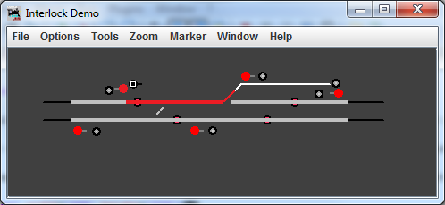
The full interlock will also set the state of the layout Blocks to use the alternative color, and the NX sensor buttons will remain in a solid active state.
If you try and set a conflicting path, then an error message will be displayed and the path will not be set.
As the Route gets cleared down by a train occupying the Blocks, so does the interlock.
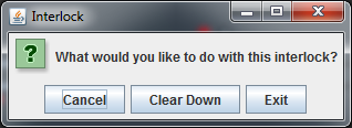
If you re-select an active interlock, the NX sensors will start to flash, and you get the option to either "Cancel" the route, "Clear Down" or "Exit".
If no Signal Masts are configured between the two points the interlock will work in very much the same way as it would with Signal Masts, it just doesn't set up or release any signals.
With all the Entry Exit methods the system will try to set the route with the lowest cost. Each layout Block has a cost assigned. It is the sum of all the block costs in a route that determine the overall route cost. By default, a Main Track is assigned a value of 50, while a side track has a value of 200. These values can be changed by the user, by editing the layout Block. If the route with the lowest cost has either another entry/exit point in the same direction, or a Block that is already set Occupied or Reserved, then it will try and find an alternative route if one is available.
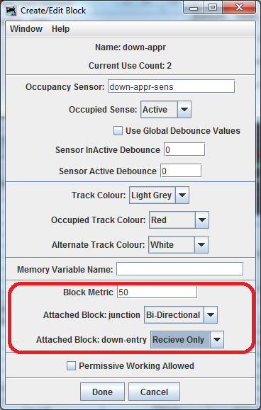
Uni-directional Blocks - It is possible to set the relationship between adjacent Blocks, to prevent routes from being set up from one block to another or vice-versa. This is set when editing the layout Block; you have the option for Both Way, to Only Send or Only Receive.
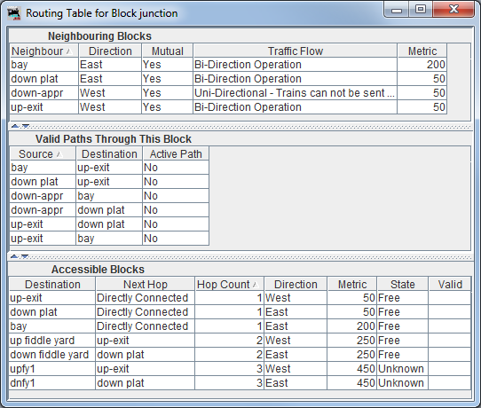
To view how a particular Block connects to other Blocks, with costs and valid Paths, right click on a track segment or turnout circle and select "View Block Routing".