JMRI contain a Speedometer tool that you can use directly from the screen or build into your own applications (see example).
The tool will report the speed of a train passing certain blocks or sensors. By checking the status of block occupany sensors or location sensors installed on your layout, and using distances between them that you have entered, the Speedometer will calculate train speed by timing between sets of sensors: Timer 1 measures between the first and second sensors (generally used for slow speeds)and Timer 2 measures between the first and third sensors (for higher speeds).
There are several approaches to specifying what type of sensors will control the Speedometer's operation:
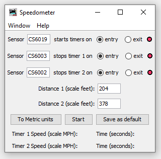
In all cases, you enter the system names of the sensors in the appropriate fields on the screen shown above, the "triggering event" (either entry or exit, when the sensor becomes Active or Inactive), and the distance between them as described in each section below. The To Metric units button will change distance to scale centimeters and speed to scale kilometers/hour.
The Start button starts the speed timing. Once you click the Start button, you can't change the configuration. If you do need to change any of the configuration, you can close the current Speedometer window and open a new one. You can also have multiple Speedometer windows open at the same time.
When a train starts to move into the field of the specified sensors, the three dots along the right side of the Speedometer window will change color to indicate sensor status:
The Timer 1 Speed and Timer 2 Speed and Time (seconds) will be displayed after the sensors are triggered by a train
An additional button, Save as default, allows you to save configuration values (except for metric/English unit conversion) that will appear in any additional or subsequent speedometers that you open. Note that if the sensors specified are not defined on your layout, the tool will automatically create them in the Sensor Table.
The most common usage is to enter the names of sensors that report occupancy (Active or Inactive indicating occupied or unocciped) for each of three blocks. Timing will start or stop depending on whether you select "entry" or "exit" for each block.
Enter the system names for the sensors that report occupancy of each of the three blocks.
The distances you enter in fields Distance 1 and Distance 2 should be measured according to whether you select "entry" or "exit" for any paticular occupancy sensor. Remember that distances should be entered in scale feet or centimeters according to your selection of units. A "scale" measure is simply the actual measure multiplied by the scale of the trains you are using, e.g. 87.1 for HO. For example, a measured two foot distance between sensors on an HO layout would be 2*87.1 = 174 scale feet.
Measure distance as follows:
If your railroad has two or more "spot" or location sensors, e.g. IR or photoresistors that record a train passing by the sensor rather than occupying a block of track, you can similarly use these sensors to trigger speedometer measurement.
Enter the system names for the sensors you wish to use for speed measurement.
The distances you enter in fields Distance 1 and Distance 2 should be measured according to whether you select "entry" or "exit" for any paticular location sensor:
You can also set up the Speedometer to measure speed across a single block or around a loop using only a single block occupancy sensor. In both cases, the same block occupancy sensor name should be entered for both the first sensor and the second sensor.
To do this, enter Sensor numbers in the three fields. This is a number (like "23") for the DCC address of the BDL16, DS54, etc. channel that will report when the occupancy changes. The simplest way to get the right number is to open a "LocoNet Monitor" window, and drop a locomotive onto the block you're interested in. You'll see the sensor message, complete with number, in the window that looks something like this:
   General sensor input report: contact 161 (DS54 20 ch1 Sw  input)
        (BDL16 10 A2) is Lo
The contact number, 161 in this case, is what you want.
There are three Sensors so you can have a shorter interval for slow speeds and a longer interval for fast speeds. The timing is from Sensor 1 to Sensor 2, and from Sensor 1 to Sensor 3.
You also need to select "on entrance" or "on exit" for each of the Sensors. This says whether the clock will start/stop when the Sensor shows the Block is first "Occupied", or when it shows the Block is first "Unoccupied".
You also enter the distance in scale feet between the various points. If you're using "on entrance", measure using the entrance end of the block.
Also check out the JMRI Help pages on: