Hardware Support: Using Arduinos with JMRI
Picture Credit: http://www.motorhomesites.org.uk
Arduino micro
controllers are special purpose computers that, with appropriate sensors and other
electronics, can be used to emulate DCC command stations and decoders, control turnout
machines, light buildings and scenery, and animate just about anything on your layout -- all
under control of JMRI.
Introduction to Using Arduinos with JMRI
Using arduinos on your layout is no harder than you want it to be. You can get a block
occupancy system up and operating and communicating with your sensors and panels in JMRI in
just a couple of hours. You can also design a custom layout animation that is triggered by
Logix or a Jython script and take days to work out all the kinks. You can even use an arduino
as your DCC command station with DCC-EX EX-CommandStation. It's up to
you.
Software to develop code on your arduino is free online at arduino.cc.
There are many ways that arduinos can be used on your railroad with JMRI:
- As a DCC command station
- As a DCC decoder installed in a locomotive
- As a DCC decoder attached to an auxiliary device, including turnouts and lights
- To detect block occupancy using current sensing, infra-red, photo-optical or other
sensors
- To control a relay to turn accessories on or off
- To directly control lights and create various lighting effects
- To control motors of various types (via optional motor control boards), such as for
moving signs, Ferris wheels, etc.
- To combine block occupancy and motor control to create triggered animations
- To control servo motors to create other types of animations, including turnout
operation, crossing gates, and many others.
JMRI provides support to use an arduino as a DCC command station ( DCC++) or as a DCC decoder (by setting up a decoder definition file. You can also use
arduinos to control one or more auxiliary devices on your railroad by connecting the arduino
to your computer running JMRI either through the tracks (in which case it will receive
commands as any other decoder) or through an auxiliary network such as C/MRI or Loconet in which
case they will communicate with JMRI by following the rules of that protocol. Sections below
will help you get started.
Additional Reference Material
You can find information about typical projects in a variety of places on the web. Some to
look at include:
- For questions about using arduinos with model railroading (including use with JMRI), go
to the "arduini" discussion group
- For examples of animations, DCC decoders, and the like, see Geoff Bunza's
blog. [Many of these can easily be adapted to communicate with JMRI.]
- For arduino code to implement a number of the topics listed above, go to this page in Github. Also, type
in search terms like "arduino," "model railroad," "DCC," and, of course, "JMRI."
- For just about anything having to do with arduinos and JMRI, go to YouTube for hundreds of videos, some with very detailed descriptions of how to
set up JMRI to interact with arduinos.
New blogs and videos are being created almost daily describing additional uses for
arduinos on the railroad. With the steady introduction of new sensors and controllers to
connect to the pins on an arduino, there is hardly an electronically controllable item that
cannot be controlled via JMRI.
[Go to top of page]
Connecting to JMRI
Arduinos communicate with your Windows, Mac, or Linux computer in a variety of ways
depending on the function they are performing:
The following sections provide hints for using some of the different communication
approaches.
Emulating a CMRI node
One of the simplest ways to have your arduino communicate with JMRI is to install software
that allows it to emulate a CMRI node. [See the CMRI help
page for information about using CMRI nodes with JMRI.] On the arduino, install one of
the arduino C/MRI libraries and include it in your sketch (for example, the library by
Michael Adams available on
Github ( see also Stephen
Brackstone's website for an example of its use). See also below for a set of steps to get up and operating with an arduino as CMRI
node with JMRI.
Some notes of interest when programming your arduino as a CMRI node:
- Be sure to set the communication speed (baud rate) the same in your arduino sketch and
in the JMRI CMRI system connection. The baud rate
will only be visible on the JMRI Preferences->Connections window if you check the box
for "Additional Connection Settings."
- When defining JMRI objects such as sensors and turnouts that are identified with CMRI
bits, JMRI starts numbering CMRI bits with 1 while common CMRI software for arduinos starts
with 0. Writing ("setting") CMRI bit 0 within an arduino sketch sets JMRI CMRI input bit 1
for the appropriate node. Thus, a JMRI Sensor named CS2001 (bit 1 on node 2) will be
controlled by setting CMRI bit 0 in the code in an arduino sketch. Reading ("getting") CMRI
bit 0 within an arduino sketch will read the bit controlling the JMRI Turnout or Light
attached to CMRI output bit 1 in JMRI, e.g. CT2001 or CL2001 (note that you cannot have
both a Light and a Turnout controlling the same output bit). See also the example setup below.
- When using arduinos to control JMRI turnouts, be mindful that JMRI's behavior is
different if the turnout is defined to have steady-state output vs. pulsed output (see
CMRI Turnout Options for more information). It is
easier to set the JMRI turnout to have steady output and use the arduino programming to
take appropriate action depending on the type of turnout switch machine you are using.
- Turnout feedback works differently for CMRI than other networks when also using fascia
panel switches as part of your operation. It is easy to program an arduino to have switches
throw your turnouts, however, JMRI behavior may not be what you expect (if you attempt to
send feedback to JMRI, JMRI will effectively ignore that and attempt to set the turnout
back to what the JMRI turnout table says it should be). See the CMRI Turnout Options for the correct information.
- The CMRI Network Manager can be used to turn on
and off communication to any CMRI node that you want, something that is useful if one or
more are temporarily taken out of service or being tested.
- When you change the state of more than one CMRI-connected device (say two turnouts) in
one Route or Logix, you can't be sure whether you will get both bits the
first time your arduino program asks for them. After a while (typically a fraction of a
second), you will, but program your arduino sketch to be sensitive to this issue.
See also the section below for a Step-by-Step example of creating
an arduino-based CMRI Node.
[Go to top of page]
Serial communication
Arduinos can be directly connected to a USB port and use serial communications via a
Jython script executed in JMRI. An example is
included in the JMRI Jython directory.
Geoff Bunza describes a serial communication script for collecting sensor data from an arduino. It is
not necessary to configure a JMRI system connection to use direct serial communications.
[Go to top of page]
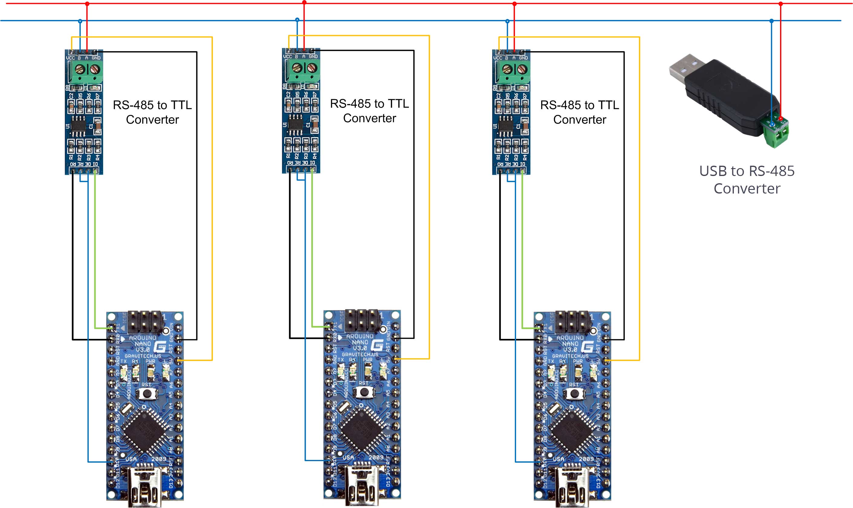
Using multiple arduinos via RS-485
 Although JMRI permits more than one CMRI connection to be
configured for a layout, it is often convenient to connect multiple arduinos on a single
CMRInet connection. This eliminates the need to have individual USB cables going from each
arduino to separate USB ports on your computer. Instead, multiple arduinos can be connected
via an RS-485 adapter to an RS-485 two wire cable in a "daisy chain" (each arduino connected
to the next), ending in an RS-485-to-USB adapter to connect to the JMRI computer as shown in
this diagram:
Although JMRI permits more than one CMRI connection to be
configured for a layout, it is often convenient to connect multiple arduinos on a single
CMRInet connection. This eliminates the need to have individual USB cables going from each
arduino to separate USB ports on your computer. Instead, multiple arduinos can be connected
via an RS-485 adapter to an RS-485 two wire cable in a "daisy chain" (each arduino connected
to the next), ending in an RS-485-to-USB adapter to connect to the JMRI computer as shown in
this diagram:
Connect each arduino to an RS-485 communication board via the serial pins on your arduino.
There are multiple sources for the RS485 communication board that range in price from a few
dollars to upwards of $30. You will also need a single USB-RS485 converter, also available
from multiple sources.
See Stephen Brackstone again for a good description of how to do this setup.
Then include a RS-485 library in your arduino sketch (for example, this one by Michael Adams). Make
sure each arduino is assigned a different CMRI node number. You do not need any additional
software on your computer. Simply tell JMRI what USB port the converter is connected to and
all arduinos on the RS485 network will be seen by JMRI.
[Go to top of page]
Using JMRI Features and Tools with Arduinos
Arduinos can be connected to almost any electronic component used on a model railroad,
including turnout motors, turnout relays, led lighting, and a wide variety of sensors. You
can, for example, define a sensor within JMRI that is
identified with a CMRI input bit and a turnout
identified with a CMRI output bit, both of which are processed by an arduino for controlling
a turnout motor. Or, you can identify those sensors and turnouts as "internal" (JMRI objects
not associated with hardware on your layout) and use a script to process the data flow back and forth to the
arduino.
Here are some examples with links to explanatory articles and/or arduino code that you can
learn from:
- Block occupancy detectors: Connect an arduino to several block occupancy detectors and
define JMRI sensors to report whether blocks are occupied. Layout panels will show tracks
changing color as blocks go from unoccupied to occupied and back again.
- Location detectors: Connect an arduino to a "point" sensor such as a photooptical
module, infrared module, Hall effect reader, RFID reader, etc. Define a JMRI sensor that
goes active when the physical sensor is active and use this to control routes, Logix, or
other JMRI "triggered" action.
- Turnout control: Connect an arduino to a turnout motor or switch machine (will require
using an auxiliary circuit board to power these devices). Define a turnout in JMRI and a
sensor for feedback. When the arduino receives a request from JMRI to thrown the turnout
(via whatever network protocol you have chosen - see above), have
the arduino throw the turnout and set the sensor.
- Multiple turnout control via serial communications: See step-by-step and code from
Geoff Bunza here.
- Logix triggering: Connect an arduino to a fascia panel switch or pushbutton. Define a
JMRI sensor that is used to trigger a Logix to do something (perhaps throw some turnouts,
set some lights, etc.). Program the arduino to set the sensor when the switch or pushbutton
is activated.
- Light or animation control: Add a motor controller to your arduino, create a JMRI light object to send a control command, create a few
sensors in JMRI for feedback, and use this sketch to
control an auxiliary motor, such as would be in a Ferris wheel. Use JMRI light objects to send commands to change speed or other
characteristics of the animation either via serial communications or using the byte
communication techniques discussed on this page.
- Speedometer: monitor the time it takes for a locomotive to trigger between two (or more
sensors), and using the distance between them, compute its speed. Send that information to
JMRI either via serial communications or using the byte communication techniques discussed
on this page.
- Car counter: using location detectors placed above the level of trucks and couplers,
write an arduino sketch to count cars as they go by. Connect to JMRI via
serial communications and write a script to write the number to a JMRI memory object which can be display on a panel showing your layout.
- DCC Decoder: Turn your arduino into an NMRI compatible decoder. Use DecoderPro to change the configuration variables.
The possibilities are nearly endless.
[Go to top of page]
Step-by-Step Example Using Arduino as a CMRI Node
This example will walk through main steps of using an arduino to monitor a block occupancy
sensor and and JMRI using that sensor to change the color of the track of the occupied
section on a layout panel. This is not meant to be a tutorial on either arduinos or JMRI, but
rather to provide a guide for someone generally familiar with both but just trying to use
them together. Much more can be found by checking some of the references listed in the Introduction above.
- First connect whichever block occupancy detector (BOD) you are using to appropriate
pins on the arduino.
- Using the arduino IDE
(integrated development environment) or other development environment, create (or
download) a sketch (arduino program) that includes the CMRI library.
- In the sketch, assign this emulated CMRI node as Node 1.
- In the sketch, use bit 0 for sending the sensor state (unoccupied=0 or occupied=1).
Some sensors will indicate an occupied block by a LOW signal on the arduino pin while
others will go HIGH - be sure you know which is which for your particular sensor so you set
the CMRI bit appropriately.
- Connect the USB port of your arduino to a USB cable and then to your computer.
- Note which USB port the arduino is connected to (on a Windows machine, for example, go
to Device Manager and see which port number pops up when you plug the arduino cable into a
USB port).
- Upload the sketch from your development environment to your arduino.
- Open JMRI PanelPro.
- Select Edit->Preferences->Connections from the pull-down menus and then "+" to
add a new connection.
- Select "CMRI" and "Serial" and then the serial port that your arduino is connected to
as shown here. NOTE: you will not be able to
simultaneously run the arduino IDE serial monitor and JMRI as whichever if opened second
will see that the port is in use.
- Check "Additional Connection Settings" and select the same "Baud rate" (serial
communications speed) that you used in the arduino sketch.
- Click on "Configure Nodes" and then "Add Node." When the "Add Node" window opens,
change the "Node Address" to 1 and click "Add Node" as shown here. Close this window and click "Done." BE SURE TO HIT
"Save" on the Preferences window.
- Open the sensor table and create a CMRI sensor
with system name 1001 (first CMRI bit on node 1)
- Open the block table and create a block. Set the
occupancy sensor to the sensor you just created.
- Go to a panel you have created and assign the block you just created to appropriate
track section.
- Run trains and watch the action!
[Go to top of page]
CBUS® is a registered trade mark of Dr Michael Bolton